Navigation System:
The Navigation System consists of several
integrated components to allow the pilot to navigate using various
methods with navigation information displayed on the Postition and
Homing Indicator (PHI). The various components are described in
the following sections.
Inertial Navigator Panel and Align Control Panel
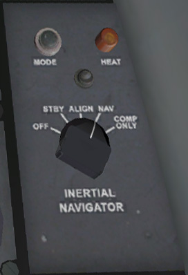
This Inertial Navigator panel on the right side panel is used to turn on the INS. Setting the switch from OFF to STBY
(Standby) sets the INS into warmup mode. This will also supply
power and heading information to the Attitude Indicator. See the Instruments section in the manual for more information on the Attitude Indicator. When the INS is placed into STBY
mode, the orange heat light on the top right of the panel will light up
indicating that the INS is warming up. The pilot must wait for
this light to extinguish before placing the INS in ALIGN mode.
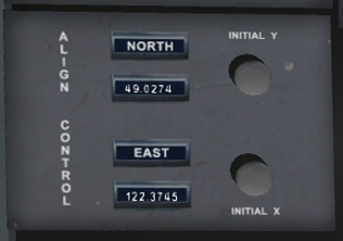
Before the INS is aligned, aircraft position is entered onto the Align
Control panel. In this simulator, this is done automatically for
you. Once in ALIGN mode,
the INS will take another minute before it aligns itself and is able to
provide naviation information. The alignment procedure is done in
two parts. After course navigation is performed, the Mode light
will turn on to solid green. Finally after final fine alignment
is complete, the Mode light will start flashing. Only after this
event occurs can the mode switch be placed into NAV mode providing
inertial navigation information to the PHI.
Note: If the aircraft is started in the simulator in a running
state, the INS will start up in the aligned state so you don't have to
perform any action to get it working.
TACAN Receiver
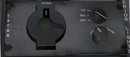
The TACAN receiver panel is located on the right side panel. The
TACAN channel may be selected by rotating the inner and outer knobs.
The TACAN channel may also be changed using the key command menu.
Push F12 - Navigation Functions - TACAN Channel and then use the +/- keys to change the channel. See the section on X-Plane Setup
to see how TACAN channels relate to VORTAC stations and how the
database is defined. The section below describes how the PHI can
be used to navigate to the selected TACAN station.
The two knobs on the right of the panel are non-functional in this simulator.
Position and Homing Indicator (PHI) and PHI/NAV Panel

The PHI is the main navigation display instrument in the CF-104.
It will display the distance and heading to a waypoint as read by
the INS or to a TACAN station defined on the TACAN control panel.
For waypoint information calculated by the INS, there is also a
small arrow on the outer ring of the compass. This shows the
wind-compensated heading the aircraft should fly to to fly directly
towards the waypoint. In the image above, this arrow is directly
above the the needle indicating that there is no crosswind component.
INS Waypoint Navigation
Once the INS has been aligned, the PHI mode on the top left can be set to IN
to read waypoint bearing information from the INS. The needle
will point to the selected waypoint and the distance in nautical miles
to the waypoint is displayed in the middle of the gauge.
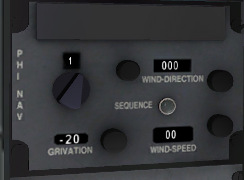
The PHI / Nav Panel allows you to cycle through the waypoints. You
can cycle through waypoints using the joystick button you configured in
the CF-104 Joystick Setup Menu. If you have not defined a joystick key
you can also use the key command menu for that. Push F12 - Navigation Functions - Waypoint Set and then use the +/- keys to cycle through the waypoints.
The Grivation value is the current magnetic variation. This is entered for you automatically in the simulator.
TACAN Navigation
To use the PHI to navigate to the selected TACAN, set the PHI Mode on the top left of the PHI to TCN.
The PHI will show distance and bearing info to the selected TACAN
assuming that it is line-of-sight of the aircraft and in reception
range.
Dead Reckoning Navigation:
Set the PHI selector switch to DR to navigate in Dead Reckoning mode.
This is primariliy used if the INS has failed. The nav
computer uses true airspeed, aircraft heading, and wind speed/direction
as set on the PHI/NAV panel to calculate the aircraft's position.
Re-alignment of INS:
Set the PHI selector
switch to set. The PHI will operate in INS mode until you change
either the distance or bearing knobs. You can use these to
reposition the INS coordinates relative to the currently-selected
waypoint. Moving the PHI selector switch out of SET will activate
the changes.
INS Route Files
The INS will read the route as defined in the file cf104_route_n.fms where n can be from 1 to 40. These files can be defined by the user and are found in the X-Plane/Output/FMS plans folder. See the X-Plane Setup
section for information on how to create your own routes. One
route is included for you that you can fly out to the Cold Lake Weapons
Range in the included Cold Lake scenery.
To select which route file to use, use the key command menu. Push F12 - Navigation Functions - Route File Select and then use the +/- keys to traverse through the routes if you have more than one defined.
Navigation Using the Supplied Scenery and Route File
TACAN Navigation:
If you've installed the Cold Lake scenery, the TACAN channel for Cold
Lake is 82. Set that on the TACAN control panel and set the PHI
selector switch on the main panel to TCN. The distance and
bearing will be displayed on the PHI.
Inertial Navigation System Navigation:
A sample route to the bombing range has been installed for you.
It can be found in the "X-Plane/Output/FMS Plans" directory and
is called "cf-104_route.fms". I'll be adding an utiility to
modify this file and to let you create other files. For now, this
is the file used by the INS for navigation. It can be edited by
hand if desired.
To follow the route, set the PHI to INS once the ILS has been aligned
and set to INS. Use the switch you configured in the joystick
setup menu to advance the waypoint or click on the waypoint switch on
the PHI/NAV panel. The PHI needle will show you the bearing and
distance to the selected waypoint. There is also an indicator
which shows the wind-corrected heading you need to follow to fly
directly to the waypoint.
Time-on-Target:
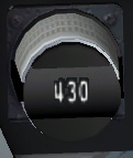
During practice missions, the time-on-target is calculated within a few
seconds. Careful mission planning is needed to determine takeoff
time and required ground speed to arrive over the target at the planned
time. To aid in this, the desired ground speed for each leg of
the route can be entered onto the Groundspeed Set Panel" (panel #10 on
the diagram). The INS computes groundspeed and the attitude
indicator has a scale on the left side. It has a marker that
moves up and down and is centered when the ground speed is equal to
that set. The top and bottom dots on this scale indicate ground
speeds of 9 knots too fast, or 9 knots too slow respectively.


