7. Normal Procedures
NOTE: Procedures highlighted in GREEN are available in X-Plane. All others are listed for informational purposes.
Video Tutorials Included in this section (more to come):
Starting Engine
Landing Pattern
7.1 After Entering Aircraft
FORWARD COCKPIT INTERIOR CHECK
- Foot retractors - Attach
- Seat belt, shoulder harness, and parachute arming cable - fasten.
WARNING
Failure to attach the straps in the following proper sequence may prevent separation from the ejection seat after ejection.
a. Place the right and left shoulder harness loops over the manual release end of the swivel link.
b. Place the automatic parachute arming cable over the manual release end of the swivel link.
c. Fasten the seat belt by locking the manual release lever.
- Oxygen hoses and other personal leads - Connect.
- Head set, oxygen mask - Connect.
- External Power - ON. Select APU Start from plugins - CF-104 Systems - Flight Preparation
Window. You'll hear the APU start and electrical power will be
available to run the instruments. The APU start cart will appear
outside.
Note
MASTER CAUTION,
INST ON EMER POWER, HYDRAULIC SYSTEM OUT, AUTO PITCH CONT OUT, NO.1 AND
NO. 2 GENERATOR OUT, CANOPY UNSAFE and ENGINE OIL LEVEL LOW lights will
be illuminated until engine is started.
- Attitude indicator - Check, large warning flag retracted.
- Left console circuit breakers - In.
- Auxillary trim selector switch - STICK TRIM.
- Auxillary trim control switch - NEUTRAL
CAUTION
- Do not use auxillary trim control without hydraulic pressure as this may damage the trim motors.
- Do not attempt to move control stick without hydraulic pressure.
- APC switch - ON and safetied.
- Stabililty control switches (roll, pitch, and yaw) - ON.
- A/R probe light rheostat - OFF.
- Pylon jettison switch - OFF.
- Engine motoring switch - OFF.
- Camera shutter switch - As required.
- IFF control panel - As required.
- External tanks refuel selector switch - As required.
- Refuel switch - OFF.
- Dual Timer Panel - As required.
- Fuel shut-off switch - ON (Guard down and secured by safety clip).
- Radar control panel - As required.
- Rudder trim - Neutral.
- Exhaust nozzle control switch - AUTO.
- Wing flap lever - UP (check indicator).
- Throttle - OFF.
- Speed brake switch - NEUTRAL.
- Red landing gear light - OFF.
- Green landing gear lights - ON.
- Landing and taxi lights - OFF.
- Anti skid - ON.
- Drag chute handle - Stowed.
- Manual landing gear release handle - Stowed.
- Armament control panel - As required.
- Rudder pedal adjustment - As required.
- Radar control switches - As required.
- Control transfer panel - As required.
- External stores rotary selector switch - SAFE.
- Canopy jettison handle - Stowed.
- Clock - Check.
- UHF channel selection - As required,
- Accelerometer - Reset.
- Airspeed setting index - Set as required.
- Mach reset - Check.
- Altimeter - Set
WARNING
It is possible
to rotate the barometric set knob through full travel so that the
10,000 foot pointer is 10,000 feet in error. Special attention
should be given the altimeter to assure that the 10,000 foot pointer is
reading correctly.
- Attitude indicators - Set.
- PHI Indicator - As required (refer to section on Navigation Equipment for more details).
- Ram air turbine handle - Stowed.
- Clearance plane and antenna tilt indicator - Check.
- External fuel quantity selector switch - As desired.
- Storm lights switch - OFF.
- Liquid oxygen gauge - Check.
- Canopy defogger - OFF.
- Fuel quantity and fuel indicating system - Check.
- Warning light system test switch - WARNING LIGHTS TEST
- Generator switches - RESET.
- Oxygen system - Check.
- Oxygen regulator panel - As desired.
- TACAN - As required.
- Exterior lights control panel - As required.
- Eject frequency override switch - OFF.
- PHI - As required.
- Inertial navigator panel - Set the INS to Align to provide nav info to the Attitude Indicator
(AI). The OFF light on the AI will go away once this is done. The INS green mode light will start
flashing when ILS alignment is complete. At this time, change the
INS mode to NAV. This normally takes about 9 minutes in the real
aircraft. In the sim, the alignment time has been shortened to
one minute.
- Pilots fresh air scoop lever - CLOSED.
- BTC - As required.
- DCU 9/A panel - As required.
- UHF - As required.
- Emergency UHF - OFF.
- Cockpit temperature - As desired.
- Cockpit temperature selector switch - AUTO.
- Flying suit switch - As desired.
- Pitot, pitch, temperature probe switch - OFF.
- Engine duct anti-ice switch - OFF
- Rain remover switch - OFF.
- Interior lights - As required.
- Align control panel - As required. The initial lat / lon coordinates are automatically
entered for you.
- Right console circuit breakers - IN.
7.2 Before Starting Engine
Before starting engine, make sure danger areas are clear of personnel,
aircraft, and vehicles. The boundary layer control outlets for
the intake ducts on each side of the lower fuselage will have a strong
suction when the engine is starting which may be strong enough to draw
articles of clothing or loose equipment into the engine. Start
engine with airplane heading into the wind when practical. An
external electrical power source will be connected when starting the
engine unless an emergency condition exists.
CAUTION
- The starter is limited to 1 minute of continuous operation, after
which 2 minutes must be allowed for cooling before using the starter
again.
- The auto-start control cable between the airplane and the
auto-start control valve must be connected so that the start switches
control starting air. If the auto-start control cable is not
connected, the pilot has no control over starting air in the event of
starter overspeed. Repeated exposure to overspeed conditions
(above 40% rpm) will cause starter fatigue and subsequent
disintegration of the starter. This can result in serious damage
to the airplane.
7.3 Starting Engine
Video Tutorial
Occasionally it may be neccessary to start the engine without the
recommended ground starting equipment. Basically there are three
types of starts that may be used. These are AUTOMATIC, MANUAL,
and BATTERY. Currently only AUTOMATIC start is supported in the
simulator.
AUTOMATIC START
The X-Plane preference to start aircraft with engine
running is used by the plugin to determine if the Starfighter will open
with the engine on or off. That option is fouund in the X-Plane - Settings - Operations and Warnings window. See the Setup Instructions on how to configure the Throttle Idle/Cutoff key and how to use the Key Command Menu.
Start the engine as follows:
-
Throttle - CUTOFF.
- Ground turbine compressor and auto-start contol cable - Connected and ON. (Done automatically for you in sim).
- Push either start switch on the left forward panel and release
(panel 2 on the Panel Layout Diagram). You may also operate the
start switch from the key command menu. Push the function key you have assigned to activate the
key command menu, select General Equipment (Option 1) and then option 3 which is
the start switch.
Note
- Successive engine starts should be alternated between ignition
systems. This procedure will serve as a check on system
operation. Make the first engine start on the No. 1 ignition
system and the second start on the No. 2 ignition system.
- The maximum starting time should not exceed 60 seconds from the time the start switch is actuated until reaching idle rpm.
- After a few
seconds the engine RPMs start increasing. When they do, push the
Idle/Cutoff function key that you have assigned, to move the
throttle from cutoff to idle.
This will cause fuel flow and the EGT should start reading to indicate
a positive start. Turning on the fuel too soon can cause a hot
start and an engine fire.
- Fuel flow 450 - 700 pounds per hour - Check 10 to 12% rpm.
- As the engine starts, system warnings will extinguish on the warning
system panel on the right forward panel (panel 7 on the Panel Layout
Diagram). The engine start sequence may be stopped by pushing
either start switch down. You may also use the key command menu option
General Equipment - Stop Start.
- Turn the radar to one of Standby mode if required. The radar
controls are on the front of the left side panel (panel 9 on the Panel
Layout Diagram). The radar take a couple of minutes to warm up before other radar modes are available so be patient.
- Turn on the reticle using the reticle power switch on the
right side of the Armament Panel. In this strike version of the
CF-104, this was displayed in a fixed position but could be adjusted
using the "Depression" dial (not functional yet). In the upcoming
conventional attack version, the sight allowed advanced computed
bombing modes such as CCIP and CCRP and the lead-computing (LCOSS)
sight for air-to-air combat.
CAUTION
- If fuel flow exceeds 700 pounds per hour, a hot
start may result. If fuel flow is less than 450 pounds per hour for
ground starts, it may be too low at altitude to accomplish an air
start. Therefore the aircraft should be cleared by maintenance
personnel before flight.
- Combustion should occur before reaching 20% rpm or within 20 seconds after fuel flow is established.
If no combustion occurs within this rpm or time limit after fuel flow
indication, or the engine fails to accelerate to normal idle rpm, or
exhaust gas temperature exceeds starting limits, a False Or Hanging Start condition has occurred. Press the start switch down to STOP-START and signal ground crew to stop air flow.
CAUTION
If
the throttle is unintentionally retarded to OFF, a flameout occurs
immediately. Do not reopen, as relight is impossible and
resultant flow of unburned fuel into the engine will create a fire
hazard.
- External electrical power and ground turbine compressor - Disconnect at idle rpm. (Done automatically for you)
- Engine instruments for proper indications - Check.
- Nozzle position - Approximately 7.5.
- Tachometer - 67% +/- 1%
- Exhaust Gas Temperature - Normal (320-420 degC)
- Oil pressure - 12 psi minimum
- Fuel flow - 1000 - 1300 lbs/hr
7.4 Ground Operation
With the assistance of ground personnel, proceed as follows:
- Generators - ON - RESET
To insure operation of the generator bus transfer circuits:
a. No. 1 generator - OFF, check warning light and RESET.
b. No. 2 generator - OFF, check warning light and RESET.
- UHF, IFF, and TACAN - As required.
- Hydraulic systems - Check
To insure that the hydraulic systems are operating properly, perform the the following checks:
- Operate speed brakes through a complete cycle. Pressure
indication on the No. 2 gauge should drop quickly to approximately 2300
psi then rise momentarily to approximately 3300 pisi and return to
normal.
- Move stabilizer only through a complete cycle. Pressure
indications should drop quickly to approximately 2700 psi then rise
momentarily to approximately 3300 pisi and return to normal.
- Move ailerons only through a complete cycle. Pressure indications should drop quickly to approximately 2600 psi then rise
momentarily to approximately 3300 pisi and return to normal.
- Move rudder through maximum travel and check that hydraulic pressure drops, rises, and returns to normal.
- Flight controls - Check for full travel.
- Trim system - Check.
CAUTION
It is possible to damage the trim
mechanism by operating the trim controls with the control stick in the
full throw position. To preclude this possibility, make all trim
system checks with control stick NEUTRAL.
Make the following checks and have the ground crew assure you that control surfaces respond correctly:
a. Rudder trim - Operate through full travel and return to neutral.
b. Aileron and horizontal stabilizer trim switch - Test (all four positions).
WARNING
An improperly installed or defective
trim switch is subject to sticking in any or all of the actuated
positions, resulting in application of extreme trim. If this
condition occurs during preflight check and the switch does not return
automatically to the center OFF position, do not fly the airplane.
Note
Take-off trim indicator lights should momentarily illuminate as the trim motors pass through the take-off setting.
- Trim - Set for takeoff and verified by ground personnel.
Note
Leading edge of horizontal stabilizer should be aligned with black "T" index painter on the vertical stabilizer.
- Auto-pitch, stick shaker, and stability control augmentation system - Check
7.5 Before Taxiiing
Observe the following instructions:
- Hydraulic door - Closed.
- Canopy - As desired.
- Ground crew interphone - Disconnected.
- Canopy initiator safety pin removed - Check.
- Ejection seat safety pin - Removed.
- Wheel chocks - Removed.
- After clear of other aircraft, external stores auto-drop system safety pins - Removed
Note
When armament stores are carried, the safety pins are to be removed in the designated area.
7.6 Taxiing
- Nose wheel steering - Engage (use Nose Wheel Steering button as configured on your stick in the CF-104 Joystick Setup menu).
The nose wheel and rudder pedals must be in the same relative position before the steering mechanism can be engaged.
WARNING
Do
not operate canopy handle at aircraft speeds in excess of 50 knots IAS
or damage to the canopy frame and locking mechanism can result.
- Brakes - Check
CAUTION
To prevent possible damage to the main landing gear wheel assemblies from excessive side-loads, avoid high speed taxi turns.
- Flight instruments and navigation equipment - Check
| BEFORE TAKE-OFF CHECK |
| H |
Harness |
Locked - Arming cable, spurs - hooked |
|
Hydraulics |
2800 - 3100 psi |
|
Hood |
Locked |
| T |
Trim |
Set for take-off |
| F |
Fuel |
Internal and External |
|
Flaps |
Take-off, speed-brakes- IN |
| G |
Gyros |
Erect and aligned |
| S |
Switches |
As required |
| C |
Controls |
Full travel |
| O |
Oxygen |
Sufficient for flight |
ENGINE CHECK
See figure 7-1 for exhaust nozzle positions at various throttle
settings. While the take-off area make the following checks:
- Align aircraft with runway - Check nose wheel centered.
- Throttle, MILITARY - Check instruments.
- RPM - 100% (plus or minus 1%).
- Exhaust gas temperature (588 degC +/- 11 degC).
Some EGT gauges may indicate a
momentary fluctuation of +/- 5 degC over normal limits. This
indication is allowable provided the fluctuation does not exceed a
maximum of +/- 5 degC and does not occur more often than once every 20
seconds.
- Nozzle position - 1 to 3.
- Fuel flow - Check
- Oil pressure - Check
- Throttle - Rapidly retard to IDLE, check for compressor stall.
- Throttle - MILITARY
- Throttle - Reduce slowly to 80% rpm, check for compressor stall
If compressor stall is encountered, abort flight.
- Throttle - Rapidly retard from 80%rpm to IDLE - Check fuel flow.
Note
Fuel
flow should momentarily drop to approximately 450-700 lb/hr. This
fuel flow indicates that sufficient minimum fuel flow will be available
during idle descents and for air starts. If the fuel flow is not
within these limits the flight should be aborted.
- Throttle - MILITARY. Advance throttle to MILITARY and check for normal engine acceleration (10 seconds maximum).
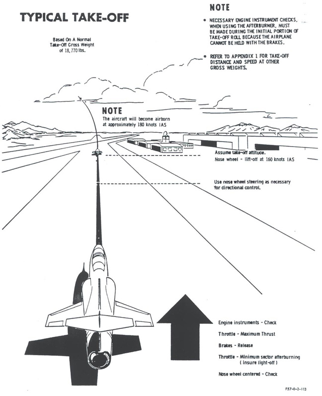
7.7 Takeoff
Prior to takeoff, set Radar to GMS or GMP ground-mapping modes or Air-toAir mode if desired.
NORMAL TAKE-OFF
- Throttle - Minimum Sector Afterburner (ensure light-off - A
successful afterburner light is by a stable EGT of 588 degC and the
nozzle opening above a value of 2).
Note
It is recommended that a stabilized afterburner light be obtained prior to advancing throttle to Maximum Afterburner.
- Brakes - Release
- Throttle - Maximum Afterburner Thrust
Note
- Maximum or Military Thrust may be used for take-off.
Military thrust take-offs however will result in extended takeoff
rolls especially if external stores are being carried.
- During afterburner take-offs avoid throttling into the sector range (nozzle position between 1.5 and 4)
- Engine instruments - Check
- Use nose wheel steering as necessary for directional control.
CAUTION
- Nose wheel steering should be disengaged prior to nose wheel lift-off to ensure proper steering clutch release.
- With the nose wheel steering system engaged, a large amount of
shimmy damping is lost; therefore, if nose wheel shimmy is encountered,
release nose wheel steering.
- Assume take-off attitude.
Note
Proper technique is to anticipate
the acceleration of the aircraft and rotate the nose so that take-off
attitude and speed are reached smoothly and simultaneously. As
external stores are added, an increase in nose wheel lift off speed can
be expected due to the change in weight and center of gravity.
Takeoff speeds can range from 180 knots to 240 knots depending on
aircraft weight, airport altitude, and weather conditions.
Maximum tire speed is 243 knots.
CROSS-WIND TAKE-OFF
In
addition to normal takeoff procedures, increase nose wheel lift-off and
take-off speed 5-10 knots to compensate for gusts. Nose wheel
steering may be required in excess of 100 knots if strong crosswinds
are present.
7.8 After Take-Off - Climb
- Landing gear lever - UP.
When airplane is definitely airborne, retract get and check red and gree landing gear position indicator lights off.
CAUTION
Immediate
retraction of the gear is important when making afterburner take-offs
to prevent exceeding the landing gear transient limit airspeed.
The landing gear doors should be completely up and locked before
the placard speed is reached; otherwise excessive airloads may damage
the mechanism, or stall gear retraction.
- Wing flap lever - UP.
Check indicator.
Note
- Do not retract wing flaps before reaching 240 knots IAS as buffeting will be experienced.
- Expect an easily controllable nose-up tendency as the flaps retract.
- Throttle - As desired. (Retard to MILITARY at minimum of 300 knots IAS)
As soon as
afterburner thrust is no longer needed, shut down the afterburner by
moving throttle aft and inboard (In X-Plane move throttle to 80%
travel). Monitor the nozzle position indicator to check that the
nozzle closes normally as the throttle is being retarded from maximum
afterburning.
- Engine instruments and fuel quantity - Check.
- Airspeed - Best climb.
7.9 Climb
The climbing
attitude with Maximum Thrust is extremely steep and until experience is
gained, some difficulty in holding the climb schedule will be
experienced. Refer to climb charts for recommended speeds to be
used during climb, and for rates of climb and fuel consumption.
CAUTION
The roll
stability augmenter should be turned off before reaching 575 knots IAS
with the tip stores installed. With tip stores installed and the
roll stability augmenter operating, wing torsional oscillations
sufficient to cause structural damage may be experienced at high
indicated airspeeds. Missile launchers are not considered as tip
stores; therefore, the roll stability augmenter should be left on when
carrying bare launchers.
7.10 Cruise
Flying Video
Refer to Appendix for Cruise Operating Data.
The windshield and canopy defogging system should be operated thoughout
the flight at the highest flow possible so that a sufficiently high
temperature is maintained to preheat the canopy and windshield areas.
It is necessary to preheat because there is insufficient time
during rapid descents to heat these areas to temperatures which prevent
the formation of frost or fog.
Note
The
auto-pitch and stick shaker may be checked in flight as follows:
While applying a slow stick deflection, note APC reading increase
in relation to angle of attack and increasing G force indicating
satisfactory system operation from sensing of vane angle. Apply a
small rapid stick deflection and note APC indicator reading increase
rapidly in relation to the pitch rate gyro. The stick deflection
should be great enough to induce a pitch rate sufficient to actuate the
stick shaker. The APC gauge reads from 0 to 5. In the real aircraft,
the stick-kicker would activate when the gauge reached 5 to let the
pilot know that he was close to the pitch-up limit. If you keep
increasing the AOA, the plane will pitch up soon after. There is
also a stick shaker which rattle the stick when you are near the stall
speed. I added a sound for this so you'll hear it a lot.
I'll let you pull the breaker in a future beta to disable the
shaker and the sound.
Maximum takeoff flap speed is M 0.85. They are
intended to be used for maneuvering. Corner velocity is between M 0.8
and M 0.85. Maximum sustained turn rate is 5.5G with flaps and 5.2 G
without.
Top speeds of up to M2.4 have been achieved in the CF-104. The
normal limit is M2.0. The top speed is limited by aerodynamic
heating. The compressor inlet temperature is monitored and a
light in the cockpit marked "SLOW" will flash when the maximum
compressor inlet temperature is exceeded which is at around M2.0 at
high altitudes but can occur at significantly lower Mach numbers at low
altitude. Prolonged flight at high CIT temperatures will cause
engine failure.
7.11 Afterburner Operation
Before moving
the throttle into the afterburner range, check that the nozzle position
indicator is in its normal range for military thrust. Move the
throttle smoothly outboard and forward into the afterburner range (last
10% of throttle travel in X-Plane). Check exhaust gas
temperature, rpm, and nozzle position.
CAUTION
If an
afterburner light is not obtained within approximately 3 seconds at sea
level or approximately 5 seconds at altitude after the throttle is
moved into the afterburner range, move the throttle inboards to
MILITARY and then after 3 to 5 seconds, return to the afterburner
range. After the initial light is obtained, move the throttle
forward with a positive motion if maximum thrust is desired.
Note
The fuel flow indicator does not indicate afterburner fuel flow.
When shutting the afterburner off,
retard the throttle aft and inboard to the Military Thrust position
(80% throttle setting in X-Plane).
7.12 Flight Characteristics
Refer to Flight Characteristics section in the manual.
7.13 Descent
Refer to Appendix for recommended descent technique and accomplish the following steps:
- Engine/duct anti-ice and pitot heat - As desired.
- Armament switches - OFF
- Radar mode selector switch - As desired.
- No.1 and No. 2 hydraulic system pressures - Check.
- Shoulder harness lever - Locked.
7.14 Before Landing
The procedures set forth below will produce the results shown in the landing chart in Appendix.
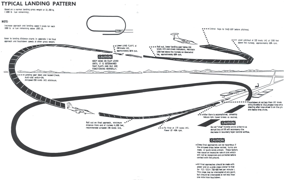
Note
The airspeeds listed herein are
based on a landing gross weight of 15,200 lbs. (1000 lbs fuel
remaining). Increase approach and landing speeds 5 knots for each
1000 lbs of fuel remaining above 1000 lbs.
INITIAL
- Wing flap lever - TAKE-OFF before pitch (check indicators).
DOWNWIND
- Landing gear lever - DOWN below 260 knots IAS (check indicators).
- Wing flap lever - LAND below 240 knots IAS and above 210 knots IAS (check indicators).
Maintain lever flight and keep hand on flap lever until it is determined that the flaps and BLC are functioning normally.
Note
A
mild roll transient may be experienced on some aircraft as flaps move
from TAKE-OFF to LAND position. This is attributed to asymmetric
diference in boudary layer control systems and will vary in intensity
and direction with individual aircraft but shot not exceed one inch of
lateral stick displacement. After the flaps are in the full down
position some lateral unbalance may persist. This unbalance can
be trimmed out, if desired.
BASE LEG TURN
- Landing gear down and locked - Check.
- Anti-skid switch - ON.
- Airspeed - 200 knots IAS minimum
FINAL
When on final approach, accomplish the following:
- Roll out on final approach, mimum distance from end of runway - 6000 feet; recommended airspeed - 190 knots IAS.
- Engine speed are required (approximately 87 - 90% rpm, but not less than 85% rpm).
- Airspeed - 170 knots IAS recommended.
Note
The
recommended final approach speed includes sufficient margin to cover
most operating conditions such as turbulent air, minor landing weight
variation, etc. This margin makes additional allowances for such
factors unnecessary.
WARNING
Under
various conditions of heavy gross weight or high ambient temperatures,
with flaps in the land position, sufficient thrust may not be available
at MILITARY to maintain proper rate of descent and airspeed during turn
from downwind to final. Refer to Heavy Weight Landing in this
section.
7.15 Landing
Video Tutorial
BOUNDARY LAYER CONTROL
The installation of boundary layer
control to effect low landing approach and touchdown speeds has
resulted in some new flight characteristics and changes in required
piloting technique. The pilot should remember, at all times, when
using land flaps that the additional lift afforded by BLC is dependent
on engine airflow. This lift, therefore varies with airspeed,
altitude, and engine rpm. The greatest effect is realized at low
airspeed, low altitude, and engine speeds above 83%, although some
effectiveness is still retained at lower power settings. The
significance of this is that under the landing condition, especially as
touchdown is approached, proper use of the throttle is mandatory to
accomplish a smooth reduction in engine rpm so that a smooth reduction
in the effects of BLC on lift will result.
LANDING TECHNIQUE
The recommended landing pattern
results in a flat powered approach similar to that used for ILS and
Radar Approach patterns carrying approximately 88% rpm until touchdown
is approached. A straight-in approach of 6000 feet minimu, is
recommended to simplify the technique and judgement involved in the
landing flare. The thrust should be controlled to hold airspeed
and sink rate to the recommended values on the final approach.
(Use of the recommended speeds provides ample speed margin from
the back side of the power required curve). Airspeed response to
throttle adjustments is extremely positive and rapid, aiding
considerably in establishing a good approach. The high drag of
the airplane in the landing configuration makes it unnecessary to use
speed brakes in the landing pattern (especially on the approach).
Speed brakes may be used during roundout to aid in controlling
touchdown point. The approach should be maintained to establish a
flare-out just short of the runway. As the touchdown point is
approached, flare-out rotation should be started, followed by a smooth
reduction in thrust to 82-83%. The gradual rpm reduction induces
a right roll-off which is associated with the thrust reduction and BLC
since a similar roll-off is experienced accompanying a thrust reduction
with take-off flaps. An abrupt thrust reduction results in abrupt
roll-off tendency and a rapid increase in sink rate. These
characteristics make it necessary to approach touchdown carrying power,
and to reduce power to idle as the main gear contacts the runway.
The smooth thrust reduction reduces roll-off tendency thereby
making it easy to maintain wings-level flight throughout the flare as
well as provide positive control of rate of sink. It may seem
unnatural to touchdown with more than idle thrust; however, with the
drag of the landing flaps, it is possible to slow down rapidly enough
so that idle thrust need not be used. Adhere to recommended
approach and touchdown speeds. If the aircraft is held of to
lower speeds, lateral stability and contro will deteriorate and wing
drop tendencies will be experienced. In addition, the high pitch
angle required for flight at these low airpseeds will be excessive and
can result in tail dragging.
NORMAL LANDING
- Throttle - Retard to IDLE (after touchdown).
- Nose wheel - Lower
- Nose wheel steering - Engage.
- Drag chute - Deploy.
To obtain maximum aerodynamic braking, deploy drag chute as soon as nose wheel is on the ground.
CAUTION
- Because of its location, the drag chute will cause a nose down
pitching moment when deployed, do not deploy the chute until all three
gear are on the ground to prevent damage to the aircraft.
- High velocity exhuast gases can fail the drag chute canopy;
therfore the drag chute should not be deployed at higher than idle rpm.
CROSS WIND LANDING
Wind drift may be compensated for
by "crabbing" or the "wind down" method, or a combination of both.
In strong crosswinds the "wing down" or a combination of the two
is more suitable. The most important things to remember are the
following: lower the nose immediately after touchdown, engage the
nose wheel steering before deploying the drag chute. The drag
chute may be deployed in 90 degree crosswinds of 20 knots or 45 degree
crosswinds of 30 knots provided the nose wheel steering is engaged.
The airplane tends to weather vane, but directional control can
be maintained with nose wheel steering. After landing,
some difficulty may be encountered releasing the drag chute; however,
turning the airplane directly into the wind should solve this problem.
HEAVY WEIGHT LANDING
When a heavy weight landing must
be made, adjust the approach and touchdown airspeeds for gross weight.
Refer to the landing charts in Appendix for the airspeed at any
landing gross weight. Fly a larger than normal pattern or make a
straight-in approach. This is especially important on approaches
under hot and/or high altitude landing conditions. Rate of
descent should be monitored closely and not allowed to become
excessive. Be prepared to use afterburning thrust if necessary.
Under marginal conditions, a straight in approach is recommended.
In addition, minimize drag by using a take-off flap or gear up
configuration for the approach, changing to the final landing
configuration when landing is assured. If landing roll distance
is a major consideration use land flaps to reduce the touchdown speed
and delay gear extension until the flare is assured.
WARNING
Under
these conditions, the afterburner will have to be used if a go-around
is attempted after the landing gear has been extended.
MINIMUM RUN LANDING
For a landing with minimum ground
roll, fly the approach so that close control can be excercised over
touch down point and airspeed. Land as near the end of the runway
as possible, touching down at 140 knots for normal landing gross
weight. Use the speed brakes to aid in controlling touchdown
point and speed as well as for maximum drag during the rollout.
Plan the chute deployment so that it blossoms as the nose wheel
touches down. Smoothly apply anti-skid brakes with constantly
increasing pedal pressure. If cycling occurs indicating maximum braking, pedal force should be reduced.
Note
Cycling of the anti-skid system can be
detected by the change in longitudinal deceleration as braking action
is automatically released and re-applied by the anti-skid system.
LANDING ON SLIPPERY RUNWAYS
Land on wet or icy runways
using the same procedure as for a minimum run landing. Leave the
flaps at LAND during the landing roll for maximum aerodynamic drag.
TOUCH AND GO LANDINGS
No special technique is required during touch and go landings.
After touchdown proceed as follow:
- Flaps - TAKE-OFF.
- Throttle - MILITARY.
- Speed brakes - IN.
- Use normal take-off technique
GO-AROUND
Make decision to go-around as soon as possible and observe the following procedures:
- Throttle - MILITARY (Maximum Thrust if necessary).
CAUTION
The
available excess thrust to perform a go around varies with gross
weight, airspeed airplane configuration, field elevation, and ambient
temperature. As extremes of these variable are approached the
ability to perform a successful go-around with Military Thrust
decreases, thus requiring afterburning thrust. Refer to Appendix
for illustrations and charts showing the variations in performance to
expect with changes in these operating conditions.
- Speed brake switch - IN.
- Landing gear lever - UP. (When definitely airborne and rate of climb is established).
- Wing flap lever - TAKE-OFF - at not less than 175 knots IAS.
Note
- Expect a definite nose-up trim change when raising the flaps to take-off.
- It is desired to raise flaps from TAKE-OFF to UP do so at not less than 240 knots IAS.
WARNING
When making a go-around, leave the wing
flap lever in the TAKE-OFF position for 30 to 60 seconds. This
action will cool the BLC ramp and keep the retracting flaps from
pinching the ramp. Pinched BLC ramps can cause undesirable
rolling moments when the BLC system is operating.
7.16 After Landing
Maintain directional control with nose wheel steering and brakes and proceed as follows:
- Speed brake switch - OUT.
- Wing flap lever - TAKE OFF - After 30 to 60 seconds, move flap lever to UP
- Rain remover - OFF
- Engine/duct anti-ice and pitot heat - OFF
- Drag chute - Jettison in appropriate area.
- Trim - Take-Off.
Note
If armament is carried, proceed to designated area for replacement of armament safety pins.
7.17 Engine Shut Down
- Electrical Equipment - OFF
- Put radar into Standby mode if on, then to off
- INS should be set to the standby mode and then off
- Run engine at three minutes at IDLE for proper engine cooling (taxi time can be included in idle time)
- Speed brakes open - Check.
- Throttle - OFF (Use throttle Idle/Cutoff function key as defined in plugins-CF-104 Systems-Joystick Config menu).
Note
- Check that engine decelerates freely. Listen for any excessive noise during shut down.
- Check speed brake closure.
7.18 Before Leaving Airplane
- Ejection seat safety pin - Installed.
- Oxygen lines - Capped and stowed.
- Wheels - Chocked.
CAUTION
In addition to establised requirements
for reporting any system defects, unusual and excessive operations, the
pilot will also make entries in appropriate form to indicate when any
limits in the Aircraft Operating Instructions have been exceeded.