9.2  RADAR:


Video Tutorial -
Air-to-Air Radar Mode

NOTE:  All sections below are taken from the CF-104 manual.  Functions not operational in the simulator or working differently are noted.

9.2.1  GENERAL

The APG 502 radar set provides the aircraft with the capability of visual or blind attack in air-to-air and air-to-ground modes.  During tactical operation, the radar is integrated with the air data computer and the vertical reference of the inertial navigation system.

The radar set provides contour and ground mapping modes for navigation and blind bombing, and tracking solutions in the air-to-air mode for visual and blind attacks against airborne targets.

The radar set performs the following operational functions:
9.2.2  AIR DATA COMPUTER

The air data computer supplies angle of attack information in the terrain avoidance mode and pressure altitude information in the ground mapping modes.

9.2.3  VERTICAL REFERENCE

The vertical reference (LN3 inertial navigator) provides aircraft pitch and roll attitude information to the radar set for radar search stabilization and for horizon lin presentation on the direct view indicator (DVI).

9.2.4  MODES OF OPERATION

The following modes of operation may be selected on the MODE SELECT switch.

9.2.4.1  STANDBY

The purpose of the standby mode is to provide the radar set with a preparatory 3-minute warm-up period.  (NOTE:  This is shorted to 20 seconds in the simulator).  No target display is presented on the radar indicator when in the standby mode.

CAUTION

Whenever the radar set is to be turned off, a 5 to 10 second pause in STBY must be observed before the MODE SELECT switch is turned to OFF.  This pause is necessary to allow time for the antenna to cage and lock onto the boresight axis.  If this procedure is not observed, the antenna will be free to swing and damage to the radar mechanical mounts can occur.

9.2.4.2  GROUND MAP SPOILED AND GROUND MAP PENCIL

In the ground map modes, the radar presents the pilot with a PPI sector display of the terrain ahead of the aircraft.  Mapping ranges of 10, 20, 40, and 80 nautical miles are available.  In the ground map spoiled (GMS) mode, the antenna provides a search pattern in elevation by means of a retactable spoiler.  In the ground map pencil (GMP) mode, the spoiler is retracted.
MODE EFFECTIVE AZ
BEAM WIDTH
ELEVATION
BEAM
WIDTH
GMP 2.2 deg 6.2 deg
GMS 2.2 deg Approx. 57 deg

NOTE:  In all other modes, azimuth beam width is 3.6 degrees and elevation beam width is 6.2 degrees.

In a typical high altitude application the pilot identifies the general area with the 80-mile sweep (NOTE:  X-Plane limitations prevent the radar from reading more than 40 Nm in front of the aircraft).  The pilot then switches to the 40-mile sweep and identifies the checkpoint.  During blind bombing modes, the pilot flies the aircraft in such a direction that the target blip is superimposed on the azimuth cursor.  In a typical blind low altitude application the pilot identifies the general area at preselected checkpoints with the 20-mile sweep.  Depending on the checkpoint, either GMP or GMS mode of operation may be selected.  The information obtained from the radar scope is used to cross-check the intertial navigation system and, if necessary, the IN system will be updated.  During blind bombing under no wind conditions, the pilot flies the aircraft in such a direction the the target blip is superimposed on the azimuth cursor.  When the blip intersects the range cursor on the display, the pilot presses the bomb release button to initiate the dual timers and completes the delivery manoeuvre.

9.2.4.3  CONTOUR MAP

Inoperative - Not calibrated

9.2.4.4  AIR-TO-AIR

In the A/A mode, the radar presents the pilot with a PPI sector display of the area ahead of the aircraft.  Search areas of 10, 20, and 40 nautical miles are available.

Two options are available ot the pilot in the air-to-air mode.  The visual acquistion method (NOT YET IMPLEMENTED) permits the pilot to automatically lock on to a target that is directly in front and between 500 and 4000 yeards in range.  This is primarily used to obtain range information on the analog bar for visual firing of guns (conventional attack version only).  The blind acquisition method permits a manually acquired lock-on at any azimuth or elevation within scope limits, and out to ranges of approximately 20 nautical miles.  A scope display of the solution (NOT YET IMPLEMENTED) directs the pilot on a curve of pursuit attack, ie, to the stern position, from which a visual or blind firing attack may be carried out.

9.2.4.5  AIR-TO-GROUND RANGING

Inoperative

9.2.4.6  GROUND-MAP EMERGENCY

The ground map emergency mode is available in the event of failure of the INS.  In this mode, the signals are the same as in GMP except that the antenna scan is caged to the aircraft armament datum line (ADL) and is not compensated for pitch or roll.

9.2.5   OPERATING CONTROLS

9.2.5.1  COCKPIT CONTROLS

The controls and indicating devices necessary for operation of the radar set are located on four cockpit panels, the pilot's control stick, and the instrument panel.

9.2.5.2  RADAR CONTROL PANEL

The radar control panel is located on the left console just aft of the throttle.  Amoung other controls, the panel contains the MODE SELECT switch which is used to connect primary power to the system.  A function description of each control is described below.


Modes Applicable
Control or Indicator Normal
Position
STBY A/A GMP GMS GME Function
MODE SELECT Switch OFF X X X X X Applies primary power to the APG-502 radar set; selects the desired mode of operation.
RANGE SWEEP Switch 20 X X X X Selects the range in miles that the range sweep on the indicator face will represent.  The range selected is shown by the RANGE light on the radar indicator control panel.  The 10 mile range is selected by operating the action reject button on the control stick with the RANGE SWEEP set at 20.  In A/A selection of 80 gives 10 mile sweep.  The action reject button is configurable in the Plugins-CF-104 Systems-Joystick Setup menu in X-Plane.
ALT SET and RANGE GATE control Detent X X X X Not yet implemented in X-Plane.  GMP, GMS, and GME modes:  When adjusted so that ground targets begin to appear at the apex of the radar indicator, targets are displayed at the ground range.  A/A mode:  Detent for visual acquistion, out of detent for blind acquistion.
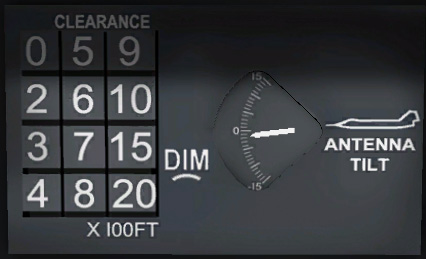
ANT TILT Control Centre X X X X Tilts the antenna up or down.  The amount of tilt in degrees is shown by the antenna tilt indicator on the clearance plane and antenna tile indicator panel to the right of the radar display.  In X-Plane, this control can be programmed to a wheel on your stick or can be controlled from the key command menu.  The dial in the virtual cockpit is inactive.  The Plugins-CF-104 Systems-Joystick Setup menu in X-Plane can be used to associate the antenna tilt function with a joystick wheel.
IF GAIN Control Full INCR X X X X Not implemented in X-Plane.
RES SEARCH SWITCH X X X X Not implemented in X-Plane.
Panel Lights N/A X X X X X Light panel indicating radar mode active.


9.2.5.3  RADAR BOMBING CONTROL PANEL


The Radar Bombing Control Panel is used to configure the radar cursors for bombing runs.  See the section on bombing missions an example on how to use this.  The panel is used in conjunction with the dual timers during radar bombing to set the initial run-in point for the bombing run.  When the target on the radar intercepts the range cursor, the pilot presses the weapon release button on the control stick to initiate the dual timer sequence and bombing maneouver.

NOTE:  All of these functions can be set using the controls in the virtual cockpit or through the key command menu.
  1. X1000 FT range selector switch - Selects range cursor display at slant angle ranges of 45,000 and 54,000 feet.  In VAR selection, provides for the setting of slant ranges by the Range Cursor control.
  2. Range Cursor Control - Sets range cursor display at variable slant range settings between 14,000 and 64,000 feet.  Range setting in increments of 100 feet is indicated on the illuminated digital dial.
  3. Offset Switch - Positions the azimuth cursor display left, right or center.
  4. Azimuth Cursor Control - NOT FUNCTIONAL in X-PLANE - Set azimuth cursor display offset in increments of 100 feet, from 0 to 30,000 feet.  Setting is indicated on the illuminated digital dial.
  5. Drift Adjust Control - Compensates for target drift by adjustment of the azimuth cursro 5 degrees left or right.

9.2.5.4  RADAR INDICATOR


Most of the radar scope functions are related to the CRT adjustment and so are not implemented in the sim.  The following controls are functional:


9.2.5.5  RADAR INDICATOR BEZEL


  1. References for the azimuth position of the radar PPI sweep, and therefore azimuth position of the antenna at +/- 45 degrees.
  2. Shows the point at which the PPI sweep should start.  Also provides a references for adjusting the ALT SET and RANGE GATE control during ground map.
  3. Provides a 900-knot reference point for the range rate gap in A/A mode.  Closing rates between 0 and 900 knots are estimated by the pilot.
  4. +/- 30 degree azimuth references for positions of the PPI sweep line.
  5. +/- 15 degree azimuth references for positions of the PPI sweep line.
  6. Indicates ranges represented by the range sweep.
  7. Reference for the time circle in A/A mode.
  8. Represents the wings of the aircraft to show the pilot which direction to correct for roll, using the artificial horizon as an indicator.

9.2.5.6  ANTENNA TILT INDICATOR


The antenna tile indicator located on the lower instrument panel, to the right of the radar display, shows the elevation angle of the antenna in all modes of operation.  The antenna tilt can be controlled from the key command menu or from a wheel on your stick or throttle if you have it configured.  See the Joystick Setup instructions for details.


9.2.5.7  ACTION/REJECT SWITCH

This switch can be assigned to a button on your throttle or control stick.  See the Joystick Setup instructions for details.

The action/reject switch, located on the stick grip, has two functions.  In all modes except for air-to-air, it is used to select 10NM scope range when the RANGE SWEEP switch is set to 20NM.  A further activation will return the scope to 20NM.

Visual Acquistion Mode (Not Yet Supported in X-Plane)
When A/A is selected on the mode selector, depression of the action/reject switch will cause the radar antenna to cease its 90 degree azimuth sweep.  If a visual acquisition is being attempted, ie. ALT SET/RANGE GATE control in detent position, the antenna will search a position along the ADL (ie. straight ahead).  At that time the range gate marker will start sweeping out from 500 to 4000 yards and will automatically lock on to the closest target illuminated by the radar beam.  To reject the target and lock onto a target further out in range, the action/reject button is pressed until the desired target is acquired.  To return to a full 90 degree azimuth search, the RES SEARCH button on the radar control panel is pressed.

Blind Acquistion Mode
When the ALT SET/RANGE GATE control is out of the detent position (always the case in X-Plane right now), depression of the action/reject button will cause the antenna to search a narrow band at the elevation position set by the elevation control and at the azimuth position of the antenna at the time the action/regject button is pressed.  The radar will lock onto the first aircraft illuminated by the radar beam.  The action/reject button may be pressed again to resume the 90 degree scan.


9.2.6  OPERATING INSTRUCTIONS

The instructions in this section are intended as a guide to airborne operation of the radar set.  The procedures covered assume adequate pre-flight check out of the radar set and satisfactory set operation.

The operating instructions are presented in a normal operating sequence.  Described first are the preliminary procedures common to all modes of operation followed by separate instructions for each mode, and then the steps necessary for the completion of a mission in one mode.  Procedures for air-to-ground ranging, contour mapping and terrain avoidance and not discussed as these features of the system are inoperative.

9.2.6.1  PRELIMINARY PROCEDURES - TURN ON

This procedure covers initial set activation and preliminary control settings and is common to all modes of operation.  It must be followed for all modes except those otherwise indicated.

To apply primary electrical power to the set, turn the MODE SELECT switch clockwise to STBY.  In X-Plane this can be done in the virtual cockpit or by using the CF-104 Key Command menu described in section 3.3.  The time delay circuits prevent tactical operation of the set during the 3-minute warm-up period (this has been shorted to 20 second in X-Plane).  The radar should not be operated in the STBY mode for longer than 15 minutes or in any other operating mode for longer than 3 minutes while the aircraft is on the ground with the engine running since serious damage can result to the radar set due to a lack of cooling air.  If the set is placed in the STBY mode just prior to taxiing, it should be "timed in" and ready to operate before take-off.

WARNING

Failure of the radar power supply may cause the potting compound within the power supply to give off a toxic smoke.  Should the radar indicator emit smoke during operation, the radar set should be immediately turned off, 100 percent O2 selected, the fresh air scoop opened and the aircraft landed as quickly as possible.

9.2.6.2  GMP / GMS OPERATION

Preliminary Control Settings

After approximately 3 minutes (20 second in the simulator), or at the button of the runway, turn the mode select switch to GMP or GMS.  No damage to the set will result from switching before the time delay period has elapsed because the time delay circuits prevent operation until the end of the period and no target returns will appear on the indicator.  When the antenna begins sweeping a one bar 90 degree scan in front of the aircraft and a search display appears on the radar indicator, the radar indicator controls should be adjusted as desired.

GMS Mode
In the following example, this is what the radar displays in GMS ground mapping mode.  The radar beam height is quite high in this mode so the beam will illuminate much of the terrain in front and below the aicraft.  You can think of the radar being like a big flash light shining on the terrain in front of it.  You can clearly see the mountain lit up by the radar beam with a big shadow behind indicating terrain that the radar can not see.  This is known as radar shadow.  This mode is very useful for ground mapping.


GMP Mode
In the following example, this is what the radar displays in GMP pencil beam mode.  The radar beam is narrow in this mode so the beam will illuminate only what is in its its path.  If the beam elevation is level, the terrain in the same elevation range of the aircraft is lit up.  In this example, the radar beam is illuminating the mountains on either side of the valley.  The valley in front of the aircraft is black indicating that there is no terrain at the current altitude.  This mode is very useful for terrain avoidance.


9.2.6.3  RADAR BOMBING ATTACK

The radar, operating in conjuction with the dual timer bombing system and the radar bombing control panel may be used to provide information for blind bombing missions.

Navigation along the planned course is accomplished by using the ground map modes.  Target area, target, or offset ID point may be identified through target study and/or indicator display predictions.

Ground Map Method
In the ground map mode, the targets are displayed in true ground range and the range cursor is slant range (NOTE:  In X-Plane, true ground range is used for the cursors as well).  The procedure is as follows:

9.2.6.4  AIR-TO-AIR MODE

The air-to-air mode provides a means of locking on to an airborne target at ranges between 500 yards, and 20NM.  The scope display presents a steering and tracking solution to the pilot to assist them in closing to a visual or blind firing position at the rear of the target.  The air-to-air more provides two methods of locking on to an airborne target, automatic lock-on (visual acquistion) and manual lock-on (blind acquistion).

NOTE:  Only blind acquistion mode is currently supported in the sim.  Visual Acquistion will be added in a future release.  If anyone undertands how the steering cues work, please let me know!

When A/A mode is selected, the functions of certain controls and operation of some systems change from those normally accepted in the ground mapping modes.  Changes common to both visual acquisition and blind acquisition are discussed in the text immediately following; changes that apply to one of these methods, are discussed with that method.

Controls

Action/Reject Button - In the air-to-air mode, the action/reject button is used to stop the antenna from sweeping through 90 degrees of azimuth and cause it to sweep 5 degrees each side of the selected azimuth.  It is also used to reject a locked-up target and achieve lock-on to another target at the same azimuth.

RANGE SWEEP Selector - In the air-to-air mode, the action/reject button no longer switches the display to or from 10NM scope range.  10NM range on the scope is obtained by selecting 80NM on the range selector.

ALT SET/RANGE GATE Control - fixed in Blind Acquistion mode in simulator

RES SEARCH Button - not yet implemented in simulator

IF GAIN Control - not implemented in simulator

Elevation Control - Any sector of the area forward of the aircraft can be searched within elevation limits of +/- 43 degrees by use of the elevation control.  Whereas in the ground mapping modes, the antenna sweeps a single bar in elevation at the elevation selected, in the air-to-air mode, the antenna sweeps a two-bar scan.  From right to left it sweeps 2 degrees below the selected elevation:  from left to right it sweeps 2 degrees above the selected elevation.  This effectively increases the elevation coverage.

The air-to-air parameters of the system are:


Operation - Visual Acquistion Mode


Not yet implemented


Operation - Blind Acquisition Mode

For the blind acquistion method of operation, the radar controls should be set as follow:

To obtain a radar lock-on using this method, the airborne target must be displayed on the radar scope and be within 20NM.  On initial contact, the target may be painted on one sweep only, ie. left to right, or right to left.  If this occurs, adjust the elevation until the target is painted on both sweeps.  If initially, the target is only seen on the right to left sweep, it must be below the selected average elevation.  In this case, lower the antenna 2 or 3 degrees until firm contact is made on both sweeps.

When the antenna sweep is approaching the target azimuth, and remember that it is sweeping 90 degrees per second, depress the action/reject button.  This will cause the antenna to stop its full 90 degree sweep and to search an area of 10 degrees in azimuth at that position.  Once a target is within 20NM and in the beam width, a lock-on should result.

NOTE:  If the antenna is not stopped at the correct azimuth or a return to full sweep is desired, the action/reject button may be pressed again to resume a full scan.